HORIZONTAL LOOP ANTENNA CONSTRUCTION
The Horizontal Loop, also known as the Loop Skywire Antenna, is an old but very effective design. Although this design has been around for a long time, it is only gaining popularity now due to the recent improvement in high power antenna tuners. The main purpose of constructing this omni directional antenna is to provide a multi band antenna which performs well from the lowest frequency band for which it is designed, all the way through 10 meters. It will usually even work well on 6 meters if your tuner and balun will handle that band. It must be understood that an antenna tuner (trans match) will be necessary for use as a multi - bander, as well as the use of twin lead feed line. I recommend 450 ohm ladder (window) line as the feed line. (See bottom of this page for types of twin lead available). You will of course need a balun near your tuner, ( I recommend a 4:1 Current Balun ), or a tuner with a built in Balun, to feed your rig’s unbalanced antenna connector. I use the MFJ- 912 (W9INN) Balun. It is a Voltage Balun, but is of good design, and works well.
How long to make it. To cut the antenna wire length to resonance we use the formula: Length (in feet) = 1005 divided by frequency (in MHz). We must subtract 4% of the total full wave length if we are using insulated wire. Example : For a 160 meter loop, 1005 divided by 1.800 (lowest 160 meter frequency in MHz) = 558 feet. If using insulated wire, shorten the overall length by 4% (-22 feet). 558 feet minus 22 feet = 536 feet. This is due to the slightly decreased velocity factor of insulated wire. The length of the feed line (450 ohm ladder line) may require some final adjustment or it may become part of the loop and serve as a radiator. My loop is 520 feet of insulated wire with a 28 foot lead in, and is resonant slightly below the bottom of the 160 meter band. I intend to shorten the insulated wire to exactly 508 feet the first time I take it down for any maintenance (Which may be a long time). You do not need to get it that close to resonance on the lowest band, but for us anal retentive types it is an interesting distraction. Use this handy Wire Antenna Calculator (Courtesy of WS6X) for all wire antennas.
Tuning. This design is a full wave (or longer) at the lowest frequency for which it is intended. It need not be cut to resonant length even for the lowest frequency band intended. It can be cut longer, even much longer, letting your tuner handle the mismatch. The most practical design however is to cut it to resonance at the lowest frequency of the lowest band targeted as outlined above. With some adjustment of the length of the feed line, you may find several bands or portions thereof which will be resonant enough to allow you to bypass the tuner. If using a separate balun to feed your tuner, try to keep the connecting coax as short as possible. 10 to 15 feet or less should not be a problem.
How High. Ideally, this antenna should be hung as high as possible, but even at very low height (as low as 10 to 20 feet above the ground) it can be very effective. Be sure to hang it high enough that it cannot be contacted by anyone on the ground. It can be hung beneath the canopy of the trees as long as the wire does not touch any leaves, branches etc. Note: If insulated wire is used, contact with leaves or branches is permissible, but is best avoided to prevent the insulation from eventually being damaged.
What if I don't have room for a 160 meter loop ? Make the loop as large as your property will allow. If you can cut it for 160 meters go for it. If not, go for 80 meters or 40 meters. A 40 meter loop requires less than 130 linear feet of insulated wire. That is a square of only 33 feet per side. Nearly any suburban residential lot should be able to accommodate that size. Remember the sides need not all be equal, it can be almost any shape that encloses the largest area possible. EXPERIMENT !
At first blush, this design may appear to be just a big short circuit because each leg of the feed line is connected to the end of a big loop of wire. True, it is a short circuit at D.C. but at Radio Frequency, which is A.C., it is an excellent radiator. Do not be misled by reports (mostly from those who have never tried it) that this is only a vertical radiator or “cloud warmer” design. When used with ladder line you will be impressed with its performance as a transmitter antenna and surprised at how quiet it is as a receiving antenna. Naturally though, performance will increase somewhat with height above ground.
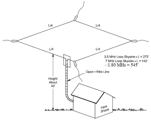
I strongly suggest the use of 12 gauge stranded, insulated, copper wire, which can be purchased at Home Depot and other home improvement centers for about $ 40 for a 520 foot roll. That is enough to make a 160 meter loop. The loop should be hung as high as is practical, and should be in the approximate shape of a big circle or square. It need not be perfectly horizontal, and the shape can really be a big square, or rectangle or any multi sided shape, so long as the two ends meet at convenient point where an insulator can be used to attach the feed line. The most critical element is that the loop should encircle the largest AREA possible. A circle, or square, or rectangle, is much better than an elongated oval, or triangle, or dog bone shape. My 160 meter loop is 7 sided, with none of the legs of equal length or height, and it is a stellar performer. It is 25 feet above ground at the highest point, and 15 feet at the lowest. Mine is 520 feet in total length.
The loop can be attached to poles, trees, buildings etc., whatever is convenient. It is best of course to try to avoid running it with a leg parallel to nearby power lines. NEVER INSTALL ANY PORTION OF THE LOOP OR FEEDER LINE ABOVE OR BELOW A POWER LINE! The loop can be free floating (that is attached so that it can be pulled tight at the two ends and just looped through the guy lines that hold it up) or it can be firmly attached at one or more points as necessary. I use heavy (5/16 in.) black Dacron rope with a knot that is loosely tied to the wire. Mine is free floating so that if I disconnect the center insulator, the entire loop will go slack, but will still be loosely attached to the guy ropes. This is probably the best way to hang it, especially if it is attached to trees, as it allows for some movement as the trees sway, and does not stress the wire. If it is left free floating or partially so, it is a good idea to leave a little slack in the wire. There is no reason to stretch the wire guitar string taut. Unless you are using a high power amplifier in a very wet environment, it is not really necessary to use insulators to attach the Dacron guy ropes to the wire when using insulated wire, as the Dacron rope does not tend to absorb much moisture. I highly recommend the use of Dacron rope due to its strength and resistance to deterioration from sunlight and the weather. This rope can be purchased from most ham radio stores and is available from MFJ, HRO, and DX Engineering. Note: This may be called Dacron, Dacron/polyester or Dacron/nylon rope, or just polyester antenna rope. It is not Paracord, and it should not be confused with Dacron wire rope, which has wire woven into it, and is sometimes used as an antenna wire. It is unlikely that you will find Dacron rope at a local hardware or home improvement store. Whatever type insulator you choose as the attachment of the two ends of the wire to the lead in, be sure to solder the antenna to the lead in wires well. I use a piece of PVC pipe as the insulator. The antenna can be fed at ANY point. I chose to feed it near the end of one leg for convenience. The feed line should be at an angle to the antenna wire, a 90 degree angle if possible to prevent coupling of the feed line to the antenna wire.
I want to stress the
importance of several points:
Remember, each end of the wire loop attaches to one of the legs of the lead in wire.
The higher above ground you can hang your antenna the better.
Enclose the largest area possible. This is the key to great performance.
For best long term results, I recommend the use of #12 insulated stranded copper wire. The best color is black, as it is sunlight resistant and less visible. This wire is also quite strong and flexible, and the insulation reduces precipitation static.
Use black Dacron rope (Not Dacron wire rope), to tie it up. Just about any other rope will rot away in a year or so. NEVER use metal wire or wire rope as it will interact with the antenna and screw things up royally. If you choose not to use Dacron rope, I suggest using heavy, non - metallic Trot Line Cord which can be found at sporting goods stores, or in catalogs catering to cat fishing enthusiasts. It is strong and rot resistant but will not last nearly as long as Dacron rope.
For best results, I recommend that you do not try to use it at a frequency lower than the lowest resonant frequency. (Don’t try to load an 80 meter loop on 160 meters) It will perform well at higher frequencies with a tuner. If you experiment with loading it on a lower than resonant frequency, try it at very low power while attempting to adjust your tuner for minimum SWR.
Do not feed It with coax unless you install an automatic, remote tuner at the antenna feedpoint. (Note: See Alternatives to Twin Lead section below). This is a MULTI band antenna, and 450 ohm ladder line will have very little loss at non resonant frequencies. Ladder line is not that difficult to deal with. You can cut a slit in your attic etc. to feed the line in. Just keep it 3 or 4 inches from any metal and don't bend it in a radius tighter than 10 or 12 inches. You can run it to a 4:1 Balun under your eaves for example, and then run a short length of coax into your shack. Experiment a bit and see what works best for you. 600 ohm open wire line will also work well, but is not as readily available, nor as easy to work with as the insulated 450 ohm window line.
If you have trouble getting it to tune to minimum SWR on any band or experience RF in the shack, try lengthening or shortening your ladder lead in line. In a worst case scenario, it may be necessary to change the position of the feed point. Some bands may exhibit lowest SWR when the tuner is bypassed. Experiment as necessary. If using a manual tuner, draw up table of the necessary tuner settings at various frequencies, for quick reference when tuning.
A word of caution: These big loop antennas are a large target for a lightning strike, either a direct or nearby hit. They can also build up a significant static charge from precipitation or dust in the atmosphere. It is crucial therefore to disconnect the lead in, and ground it (direct to ground outside the shack if possible), before an electrical storm approaches. To prevent equipment damage from static charge buildup, always ground both leads of the window line, (or center wire and braid if using a coax run to your tuner) together momentarily, before connecting the feed line to your tuner or an antenna analyzer.
Here are instructions on building a HOME BREW WINDOW LINE FEED POINT INSULATOR.-----
Bird's
eye view of my horizontal
loop antenna setup.
-----
Here is a
link
to an
outstanding article regarding the use of ladder line: Article by Steve Ford
WB8IMY courtesy of W1MV. Check it out.
-----
Types Of Twin Lead
| 300 Ohm Twin Lead | 450 Ohm Window Line |
True Ladder Line Normally 600 Ohm |
| Also Called TV Lead In | Also Called Ladder Line | Also Called Open Wire Line |
|
|
 |
 |
Alternatives to Twin Lead
For those reluctant to use twin lead, there are several new alternatives, which allow the use of coax feedline, with minimal losses, even on non resonant frequencies.
MFJ has recently introduced two new remote high power tuners. These are the MFJ-998RT, rated at 1,500 watts SSB & CW, and the similar MFJ-994BRT, rated at 600 watts. Click below to view them in the latest MFJ Catalog. These tuners are claimed to be completely weather sealed, and are powered through the coax feedline via an included power injector. Both units are designed for use from 160 through 10 meters.
These are relatively new products, but I have had good reports on them.


LDG Electronics also makes a remote tuner, the RT-100 tuner that can handle 100 watts. These are fairly new products, and I have not yet seen any reviews of them. If anyone tries them out, please e-mail me and let me know how they perform.
Frequently Asked Questions

Q. Why do you recommend a 4:1 balun when using 450 ohm or 600 ohm feed line?
A. The 4:1 balun is readily available, and offers the best overall compromise for a multiple band loop antenna. It will normally provide an impedance which your tuner can work with at all frequencies for which your antenna is designed. Remember that the impedance listed for feed line in only its characteristic impedance. The actual impedance varies with the frequency of the signal. A 1:1 balun will probably work with most antenna systems.
Q. Which is best, a voltage balun or current balun ?
A.
A current balun has some advantages
regarding efficiency and core saturation issues. A good voltage balun,
rated for the power you intend to run will work quite well in most
circumstances. I recommend using a voltage balun if you already have one. If you
are buying a new one, a current balun will be a slightly better choice in the
long run. For more information see this article by Tom, W8JI.
Baluns - Choosing The Correct Balun.
Q. Why do you recommend the 450 ohm window line instead of open wire or 300 ohm TV twin lead ?
A. Even though it has slightly more loss, the ladder line is easier to work with, and more readily available than true open wire line. The TV twin lead has too much loss, and will not handle very much power.
Q. I want
to make my own open wire feedline. Where can I find information?
A.
Check out these links, and bear in mind if you will be
using it as a multi band antenna system and using a tuner.
Q.
How long should my twin lead feed line be ?
A.
Long enough to reach your tuner or balun, plus a few additional feet for
trimming.
Good lengths (in feet): Somewhere around 40,
80, 110, etc.
Lengths to avoid (in feet): 32, 65, 96, 130, and 260 - and
multiples of any of those. If in doubt, consult the ARRL Antenna Book.
Having said that, I recommend that you simply make it a bit longer than
necessary, as previously stated. Then, if it won't tune on a certain part of a
band or bands, or if you experience RF in the shack, shorten
the feed line a foot or so at a time until you hit the sweet spot and overcome
the problem. An antenna analyzer will be of great value here. Although it is
easier to cut the line to shorten it, all twin lead can be lengthened by
splicing. Just do a good soldering job, and seal the splice with epoxy or liquid
electrical tape, or use the DX Engineering Ladder Line Coupler
https://www.dxengineering.com/parts/dxe-llc-1p. If using coax as your feed line,
(not recommended) don't worry about the
length. Just use a long enough run to reach your shack.
Q. What
should I do with the extra length of twin lead if I hit the sweet spot and don't
want to shorten it ?
A.
Run it back and forth in a zig-zag pattern, or in large loose coils away from
any conducting material. Do not coil or roll it back up on itself.

Q. Can I make an attic loop
antenna, or a loop around the perimeter of my roof ?
A.
You sure can, and in this era of CC&R antenna
restrictions, it may be your only choice. Of course it will not work as well as
one up clear and high in the air, but you will probably be surprised at how well
it works. It will be better than almost any other stealth type antenna, if you
have room for it. Try to keep the antenna wire a few inches off the roof by
short PVC or wooden standoffs, or hang it under the eaves. Naturally, as with
any other near house antenna, you may experience some RFI issues both to and
from household wiring and appliances, but IF you have such problems, they can
normally be cured by the judicious use of chokes and toroids. The ARRL RFI
Book is an excellent reference on how to avoid and cure such potential
problems.
Q. Can you help me understand why twin lead is a much better choice than coax for feed line on multi band or other non resonant antennas ? Doesn't the tuner transform the impedance to 50 ohms and bring the SWR down just as well with coax ?
A. When you are using coaxial cable under high (greater than 3:1) SWR conditions, the tuner may provide the 50 ohm match to your radio, but the mismatch and HIGH SWR still exists between the antenna tuner and the antenna! This translates to very high losses in the coaxial cable. At HF frequencies, the loss in ladder line is so low, you can still see good results even when the SWR between your tuner and antenna feed point is horrendous. The antenna tuner provides the 50 ohm match to your radio, and you really don’t care what the SWR is between the tuner and the antenna, due to the inherent low loss of twin lead. Use this handy On - Line Calculator to determine coax loss. On - Line Coax Cable Loss / Antenna Gain Calculator.
Q. Will the built in auto tuner in my transceiver be sufficient for use on a multi band loop antenna ?
A. Unfortunately
it probably will not. Those tuners are only capable of handling a mismatch of about 3:1
or so. You will be encountering much higher ratios than that, hence the need for
a good stand alone tuner. Most manual and automatic tuners on the market today
will do a good job, as long as they are capable of handling the power levels you
will be running (in the future as well as when starting out).
Q. I already have a horizontal loop fed with coax. I am able to obtain a low SWR reading on all the bands at and above the fundamental frequency, using my stand alone tuner, but the antenna does not seem to perform well on several bands. How can I determine which bands will most improve by changing to twin lead ?
A. With your tuner bypassed, use either an antenna analyzer, or your radio’s SWR meter, and measure the SWR at various points throughout the 80 to 10 meter bands. Those frequencies where you have SWR of about 3:1 or higher are the spots where you will most benefit from the use of twin lead.Bear in mind that when your tuner is used, SWR indications can be adjusted to near 1:1 on most bands, even using coax as your lead in. That is because you are only measuring the SWR between tuner and radio. That will keep your modern solid state radio happy seeing about 50 ohms, so it will produce full power without folding back power to protect your finals. However, when using coax on the non resonant frequencies, most of that power is not radiated, since it is simply wasted heating up your coax.When you change to using twin lead, most of that same power will not be wasted, but will radiate from your antenna due to the inherently low loss of twin lead, even at non resonant frequencies. The Standing Wave will still actually be present on your twin lead, but it does not matter since it will make it to your antenna where it will radiate. You won’t see the difference on your power meter or SWR meter, but you will be putting out a much stronger signal, and should get good signal reports. You will also notice a marked improvement on received signals.
As a reminder, if you have trouble getting good SWR readings on some frequencies, experiment by slightly changing the length of your twin lead, or in severe cases even relocating the feed point.
Q. How
much power do I actually lose with coax VS twin lead ?
A. Assume that you have a 100-W transceiver connected to one of the transmission lines listed below. How much power (in watts)
actually makes it to your antenna ? Examples are shown for 80, 10 and 2 meters, with 100 feet of transmission line and SWRs of 1:1
and 6:1 on each of these bands. Remember that SWR can easily exceed 10:1, and is often even much higher, on a non resonant (multi band) antenna.
TABLE: SWR Power Loss For Various Types Of Transmission
Cables
Note: These losses are in DECIBELS, not percentage of
power.
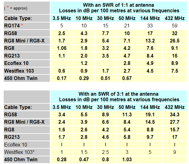

It’s worth noting that ladder line exhibits substantially less loss on the HF bands than just about any other transmission line available. This means you can get away with SWRs on ladder line that would cause intolerable loss with coax.
The object of any antenna system is to get RF into the antenna, and out on the air. Your transmission line plays a critical role in getting this job done. When you shortchange yourself on transmission line, you shortchange your whole station. As long as an antenna tuner is used, ladder line offers some compelling advantages compared with coaxial cable in almost any medium- or high-frequency application. This is particularly true when you want multiband operation with a single antenna.
Q. Is the increased performance of a twin lead fed, multi band antenna really worth the effort VS coax fed ?
A. See the excerpt below, from "Understanding SWR By Example" by Darrin Walraven, as published in the November 2006 issue of QST Magazine, and judge for yourself.

READ & UNDERSTAND THIS !


-----
Good luck with your project. Chances are you will be so pleased with this antenna that you will no longer use any other wire antenna at or above the resonant range of your Horizontal Loop. Please let me know how it works for YOU. If I can be of any assistance, please e-mail me but first, please read the Frequently Asked Questions section above.-----
Recommended Reading

Some links to articles and information that will provide valuable insight regarding antenna systems:
How To Use An Antenna Tuner - hamuniverse.com
5 Simple Multi Band Wire Antennas
Antenna Tuner Matching Problems And Suggested Feedline Lengths
Understanding Antennas For The Non-Technical Ham By W9INN
Balun and Unun Core Material Selection
By Balun Designs

![]()
Website authored and designed by Randy Davis - Webmster
Copyright © 2006 / 2013 / 2121 by Randy Davis.
All rights reserved.
All information on this website may be copied or reproduced and used for
NON
- commercial purposes only.
RETURN TO TOP OF PAGE
RETURN TO HOME PAGE
